(4) An yet it moves - part 1

Build Update: I had to cut short the screws that attach the support rods to the carriages because the screws were in the path of the timing belt.(I will update the BOM at the end of the project.)

I thought about a title of this building phase and I remembered about Galileo Galilei words "Eppur si muove".
He was talking about the Earth orbiting around the Sun, but at the end of this phase I would to say it about my Kossel 3d Priter before starting the calibration process.

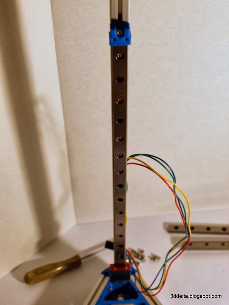
So after couple of weeks of waiting I finally got my linear rails. I did not plat to use all the screws to connect the rails so I choose one on, one off pattern, but the number of holes does not match my pattern, so i got what you can see in the picture.
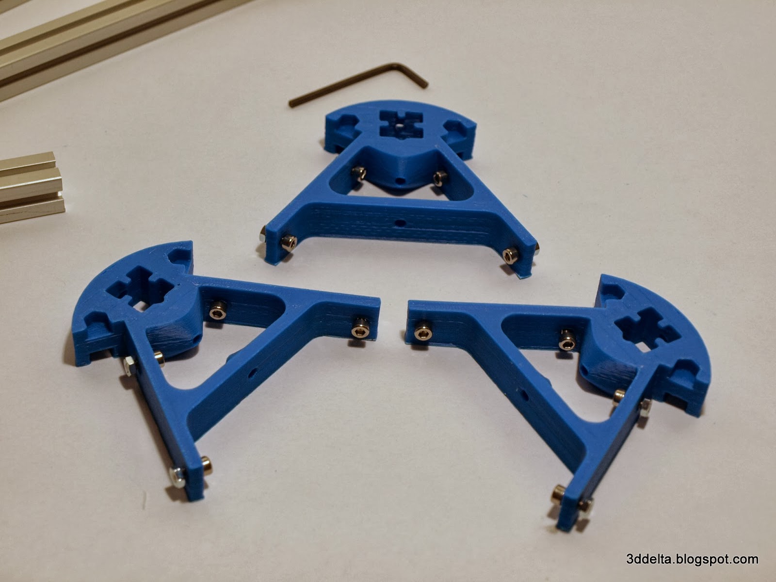
To fit the linear rails over the vertical towers you will have to remove the top support triangle. Attach the M3 8mm screws to the rails and the six plastic rails end supports. Slide the plastic rails end and the rails as in views 36 and 37.

View 36
View 37

(3) Rectangles and Parallelograms - part 3

After adding the motors to the base is time to finish assembling the rest of the aluminium extrusions. To connect with the printed corners two M3 8mm screws are used in each corner. Use a needle nose pliers (curved ones are better) to fit the nut on the screw inside the channel for the aluminum extrusion.
See images below for more details.

View 22
View 23
View 24

The trickiest part from all the build until now was to insert the vertical towers into the slots. You will have to stir clear of the motor wires and fit them to the extrusion channel. Also fit the M3 nuts into the opposite channel.

In the end tight and secure the M3 screws with the Allen wrench. Your build should look like mine in views 25 and 26.

View 25
View 26

In the same way add the M3 screw to each of the top corners and temporary attach the top triangle to the vertical towers. (You will have to remove the top to attach the belt idler and tensioner screw.)

(2) Rectangles and Parallelograms - part 2

Now that the base is assembled lets start with the top. Most likely the top printed corners will have plastic excess on the bottom side. You can identify the top and bottom of the printed corners by the belt tensioner screw hole. The bottom side has a hexagonal nut hole.

Use a hobby knife to trim the excess plastic, see views 14 and 15.

View 14
View 15

The assembly process is similar with the one of the base. The next views illustrate step by step bringing the printed corners and the aluminum extrusions together.

View 16
View 17
View 18
View 19
View 20
View 21

Once all the parts are brought together use the 3mm Allen wrench to tight all the screws and secure the aluminum extrusions to the printed plastic corners.

We are coming back to the base assembly to attach the stepper motors.