This Phase is entitled rectangles and parallelograms because the structure and kinematics of a linear delta 3D printer is all about rectangles and parallelograms.
As you can see in the diagram below the rectangles formed by the vertical linear rails and the base and top of the printer constitute the support structure of the printer.

The vertical linear rails are uuh vertical, limiting the motion of the carriages up and down. The carriages are designed and built with an important characteristic - the two connection points for the effector support rods have to be on a horizontal axis. With the opposite sides of a parallelogram being parallel this keeps the effector platform parallel with the printing bed.
No automatic calibration can substitute a good build.
Before going any further I need to make a disclaimer:
This is my first project of assembling a 3D printer, all the blog posts are the result of my build process, my readings and common sense. If you already built your printer please comment, if you want to build your mini Kossel use your own judgement to follow my methods.Most important always think safety first: be careful with hand tools (screwdrivers, knives, files etc.) or power tools (power drill, soldering iron, etc.); wear protection goggles if needed.
This is my first project of assembling a 3D printer, all the blog posts are the result of my build process, my readings and common sense. If you already built your printer please comment, if you want to build your mini Kossel use your own judgement to follow my methods.Most important always think safety first: be careful with hand tools (screwdrivers, knives, files etc.) or power tools (power drill, soldering iron, etc.); wear protection goggles if needed.
I got some parts in, a lot of them ordered and on the way (you can follow the progress on the bill of materials page) , but I had the major parts to start assembling.
So let's start building...
Gather the parts for the base assembly, use a well lit area, and a white paper pad.
For the base you will need the three base corners, 6 horizontal aluminum extrusions, 24) M3 - 8mm socket head screws with M3 nuts, and an Allen wrench.
For the base you will need the three base corners, 6 horizontal aluminum extrusions, 24) M3 - 8mm socket head screws with M3 nuts, and an Allen wrench.

Before assembling get a file and clean any excess plastic on the printed parts and especially a cylindrical file to make sure the screws can rotate freely in the holes. (You do not want to tight the screws by creating a thread in the printed piece and not tightening the 3mm nut.)
Note: I got my files from Harbor Freight Tools store - $3 for a set of six small files.
I also got a set of metric Allen wrenches.
Tools Used
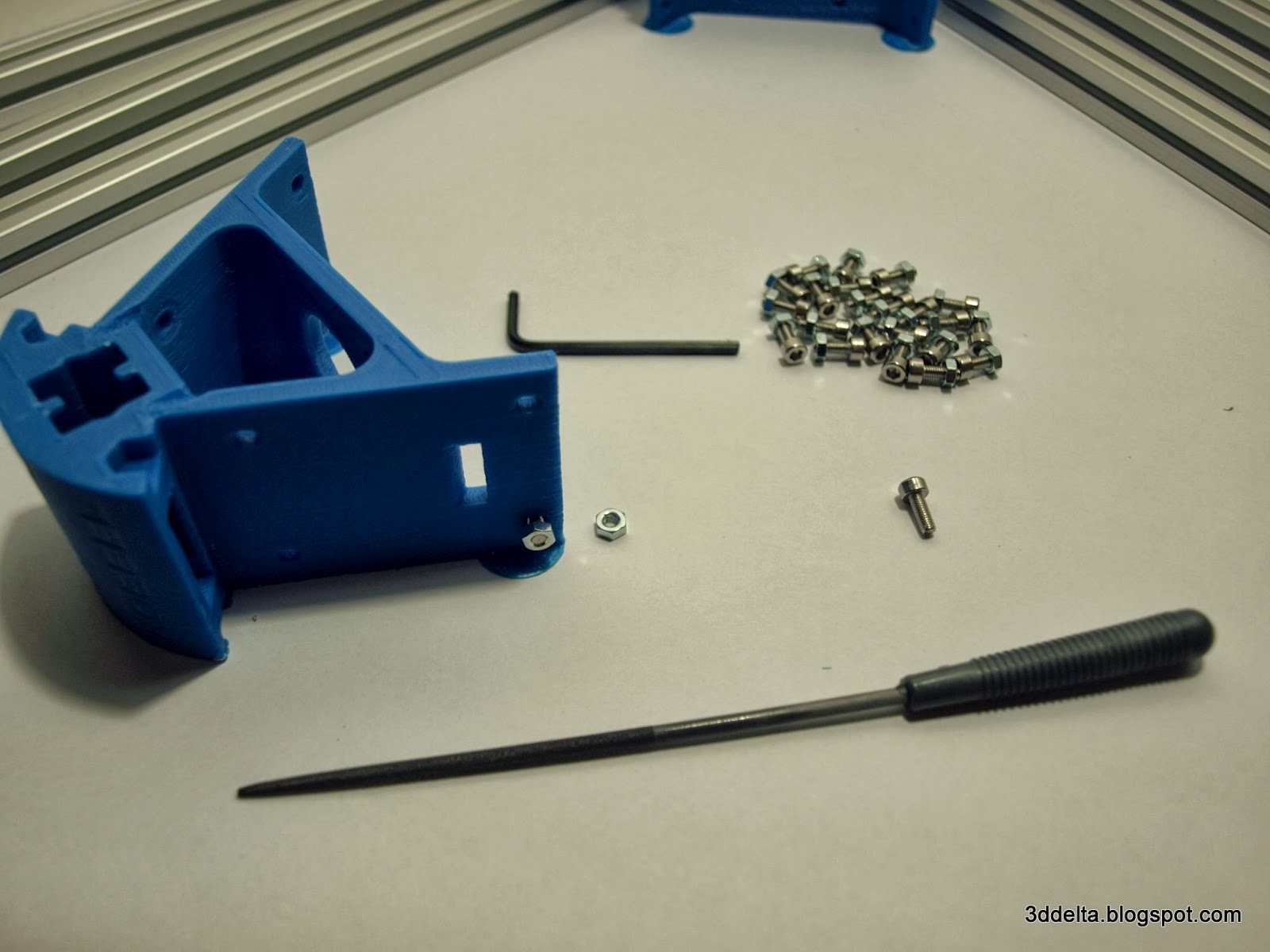 |
File screw hols
 |
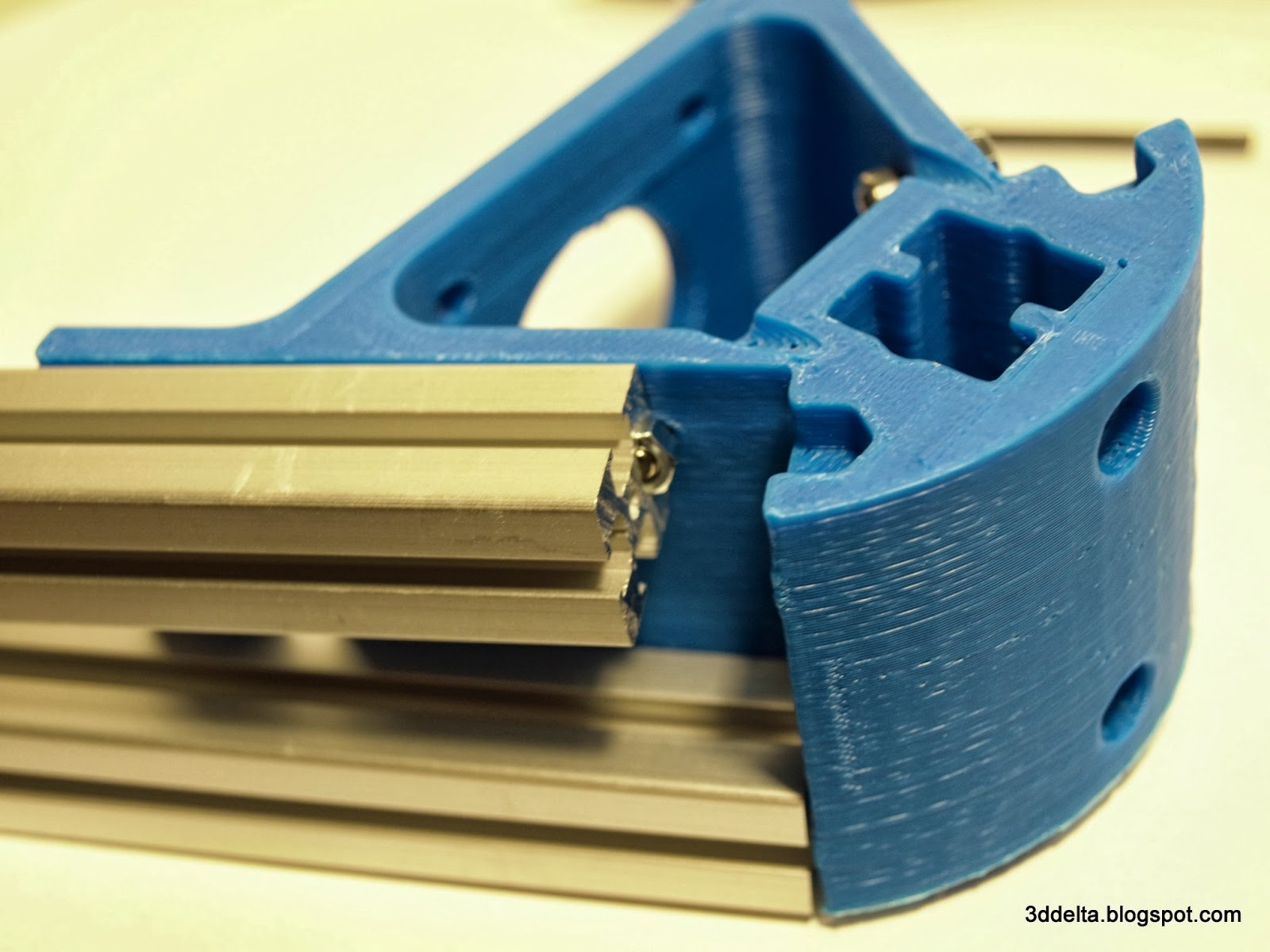
Insert screws in all eight holes in each corner and insert nuts by hand, tight only couple of threads.
View 1
 |
View 2
 |
Insert both base aluminum profiles into the printed corners like in the pictures. (I am a right handed so I put the corners on the right.) You should end up like the image in View 5.
View 3
 |
View 4
 |
View 5
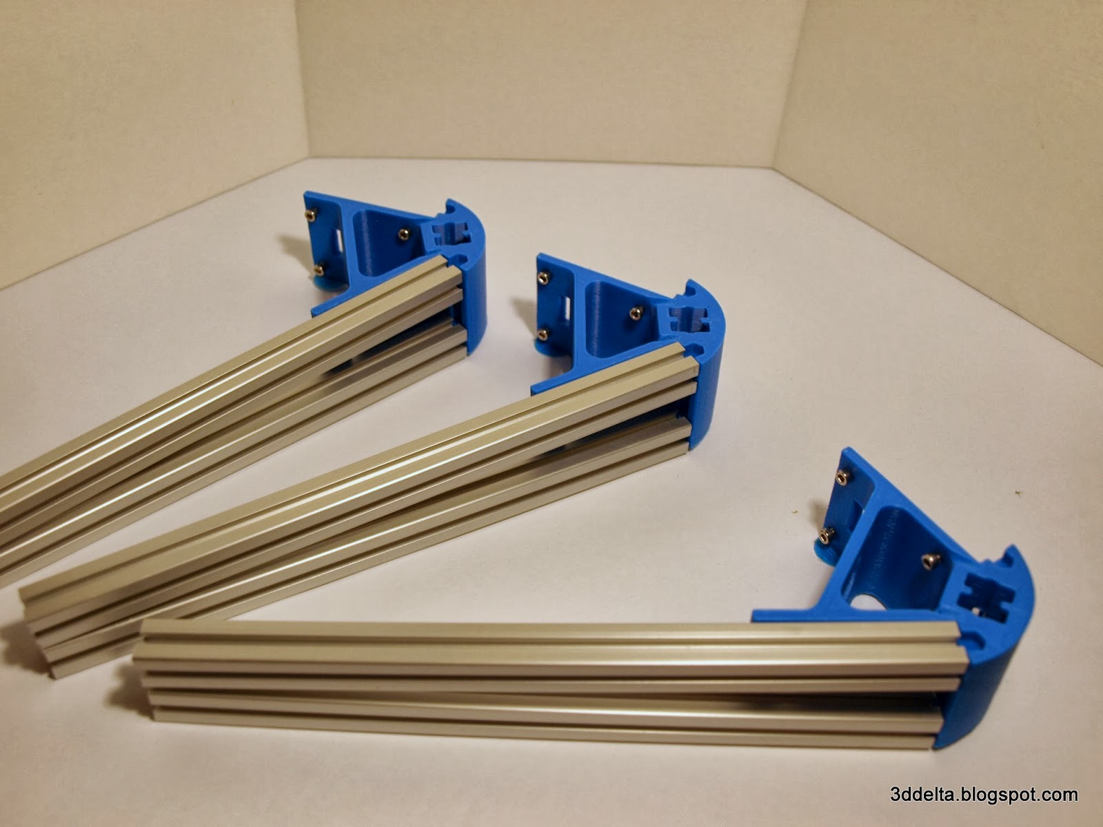 |
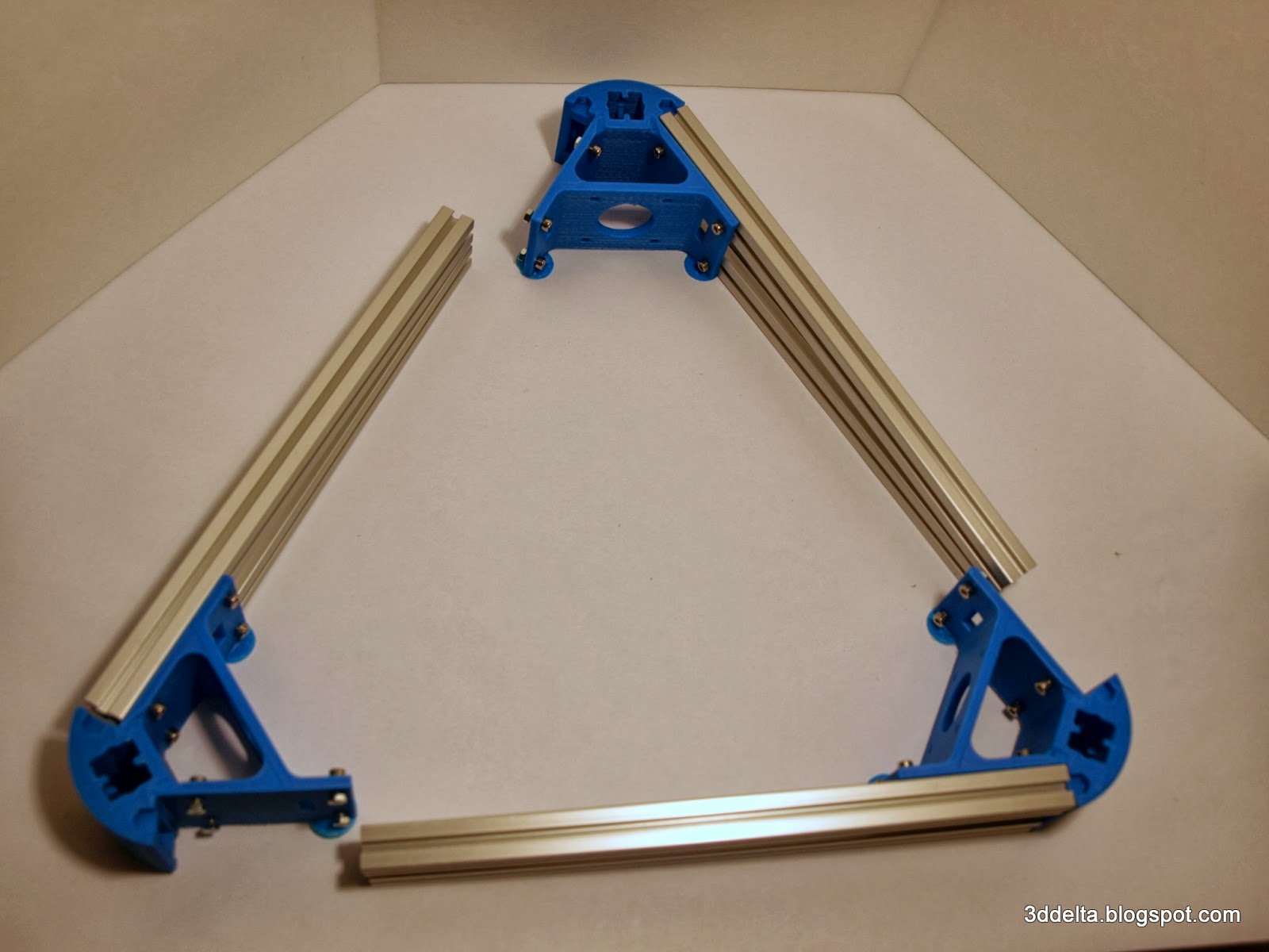
I looked at different ways to assemble the base, but they looked cumbersome. It came to me to do all three sides together and close the triangle step by step. I hope the next six next pictures help.
View 6
 |
View 7
 |
View 8
 |
View 9
 |
View 10
 |
View 11
 |
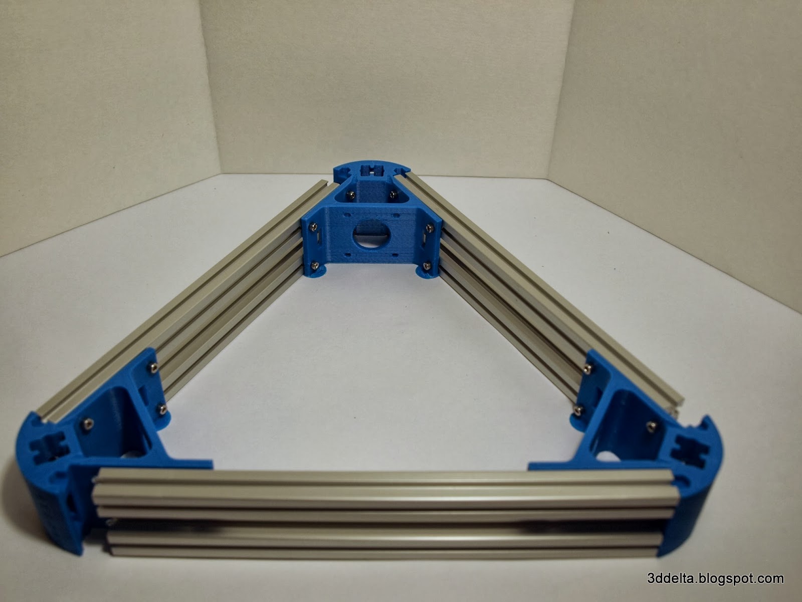
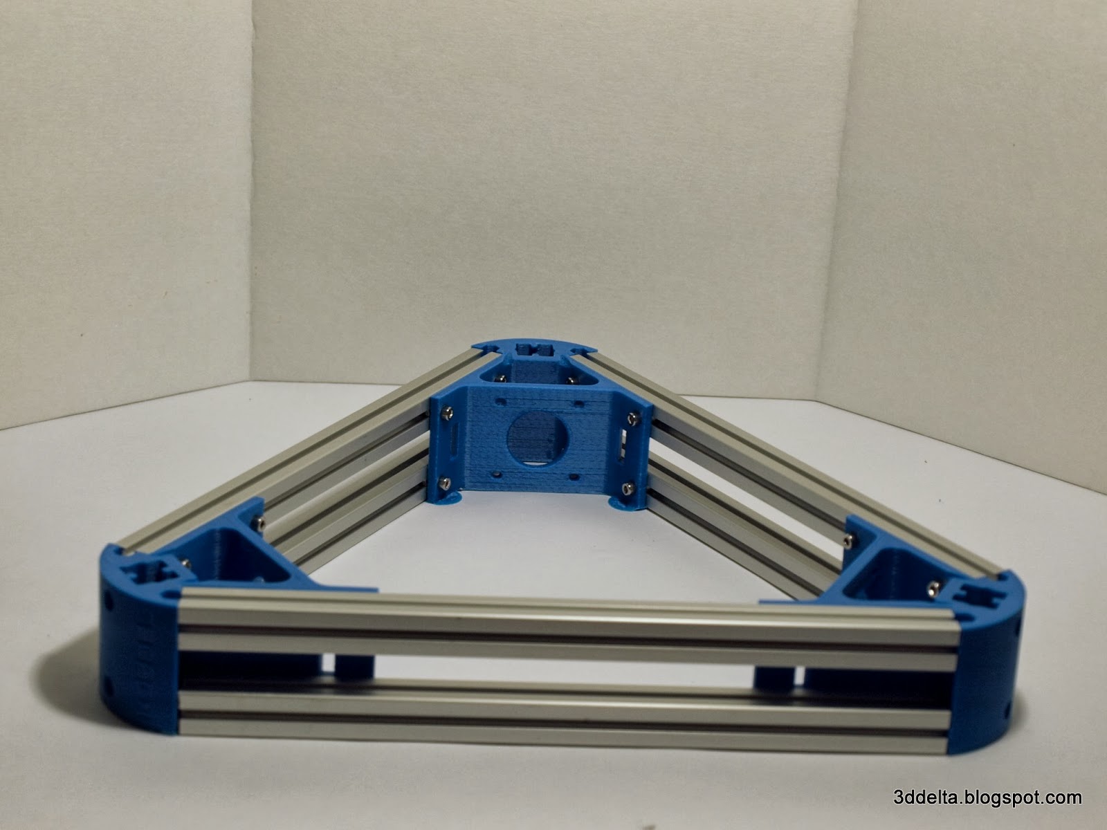
Once everything put together use the 3mm Allen wrench to tight all the screws that secure the aluminum extrusions to the printed corners. See views 12 and 13.
View 12
 |
View 13
 |
Now that you have the base assembled, gather the top corner pieces, the other three horizontal aluminum extrusions, 12) M3 - 8mm socket head screws with M3 nuts, and the 3mm Allen wrench.
Assembling the top triangle will be covered in the part 2 of Phase I.
No comments:
Post a Comment