(5) And yet it moves - part 2

It took a while to get to write this page because setting up the Sanguinololu electronics was a painful process.
If I will build another printer I will choose a more beaten path - Arduino Mega with Ramps and motor drivers.

I shortly realized that there is no bootloader on the Sanguinololu's Atmega1284p, so I bought a $7 USBasp programmer from ebay. I tried to follow the instructions from USBasp programmer for Sanguinololu page, but no success. You can see my setup below (NOTE: Do Not power the Sanguinololu board, the chip will be powered by the programmer)
My patch between the programmer and the Sanguinololu was:

Function USBasp Programmer Output Sanguinololu ISP header
MISO 9 1
VCC +5V 2 2
SCK 7 3
MOSI 1 4
RESET 5 5
GDN 10 6

After I exhausted all options that I could think about I decided to buy a Arduino Uno to use it as a programmer and use the approach from this Burning the Sanguino Bootloader using Arduino as ISP page, but patching to the Sanguinololu board directly, because I did not have all the electronic components, using the following patch table:
Function Arduino UNO Pins Sanguinololu ISP header
MISO 12 1
VCC +5V 5Vcc 2
SCK 13 3
MOSI 11 4
RESET 10 5
GDN GDN 6
And you can see my new setup:

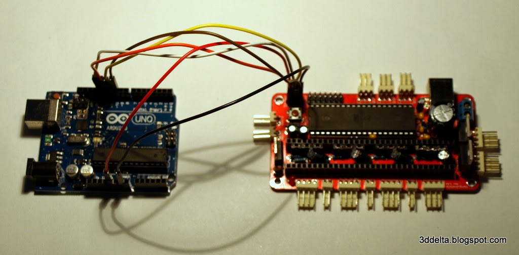
This din not work either.

(4) An yet it moves - part 1

Build Update: I had to cut short the screws that attach the support rods to the carriages because the screws were in the path of the timing belt.(I will update the BOM at the end of the project.)

I thought about a title of this building phase and I remembered about Galileo Galilei words "Eppur si muove".
He was talking about the Earth orbiting around the Sun, but at the end of this phase I would to say it about my Kossel 3d Priter before starting the calibration process.

So after couple of weeks of waiting I finally got my linear rails. I did not plat to use all the screws to connect the rails so I choose one on, one off pattern, but the number of holes does not match my pattern, so i got what you can see in the picture.
To fit the linear rails over the vertical towers you will have to remove the top support triangle. Attach the M3 8mm screws to the rails and the six plastic rails end supports. Slide the plastic rails end and the rails as in views 36 and 37.

View 36
View 37

(3) Rectangles and Parallelograms - part 3

After adding the motors to the base is time to finish assembling the rest of the aluminium extrusions. To connect with the printed corners two M3 8mm screws are used in each corner. Use a needle nose pliers (curved ones are better) to fit the nut on the screw inside the channel for the aluminum extrusion.
See images below for more details.

View 22
View 23
View 24

The trickiest part from all the build until now was to insert the vertical towers into the slots. You will have to stir clear of the motor wires and fit them to the extrusion channel. Also fit the M3 nuts into the opposite channel.

In the end tight and secure the M3 screws with the Allen wrench. Your build should look like mine in views 25 and 26.

View 25
View 26

In the same way add the M3 screw to each of the top corners and temporary attach the top triangle to the vertical towers. (You will have to remove the top to attach the belt idler and tensioner screw.)

(2) Rectangles and Parallelograms - part 2

Now that the base is assembled lets start with the top. Most likely the top printed corners will have plastic excess on the bottom side. You can identify the top and bottom of the printed corners by the belt tensioner screw hole. The bottom side has a hexagonal nut hole.

Use a hobby knife to trim the excess plastic, see views 14 and 15.

View 14
View 15

The assembly process is similar with the one of the base. The next views illustrate step by step bringing the printed corners and the aluminum extrusions together.

View 16
View 17
View 18
View 19
View 20
View 21

Once all the parts are brought together use the 3mm Allen wrench to tight all the screws and secure the aluminum extrusions to the printed plastic corners.

We are coming back to the base assembly to attach the stepper motors.

(1) Rectangles and parallelograms - part 1


This Phase is entitled rectangles and parallelograms because the structure and kinematics of a linear delta 3D printer is all about rectangles and parallelograms.
As you can see in the diagram below the rectangles formed by the vertical linear rails and the base and top of the printer constitute the support structure of the printer.
The vertical linear rails are uuh vertical, limiting the motion of the carriages up and down. The carriages are designed and built with an important characteristic - the two connection points for the effector support rods have to be on a horizontal axis. With the opposite sides of a parallelogram being  parallel this keeps the effector platform parallel with the printing bed.
No automatic calibration can substitute a good build.

Before going any further I need to make a disclaimer:
This is my first project of assembling a 3D printer, all the blog posts are the result of my build process, my readings and common sense. If you already built your printer please comment, if you want to build your mini Kossel use your own judgement to follow my methods.Most important always think safety first: be careful with hand tools (screwdrivers, knives, files etc.) or power tools (power drill, soldering iron, etc.); wear protection goggles if needed.

I got some parts in, a lot of them ordered and on the way (you can follow the progress on the bill of materials page) , but I had the major parts to start assembling.

So let's start building...

Gather the parts for the base assembly, use a well lit area, and a white paper pad.
For the base you will need the three base corners, 6 horizontal aluminum extrusions, 24) M3 - 8mm socket head screws with M3 nuts, and an Allen wrench.