Use a hobby knife to trim the excess plastic, see views 14 and 15.
View 14
 |
View 15
 |
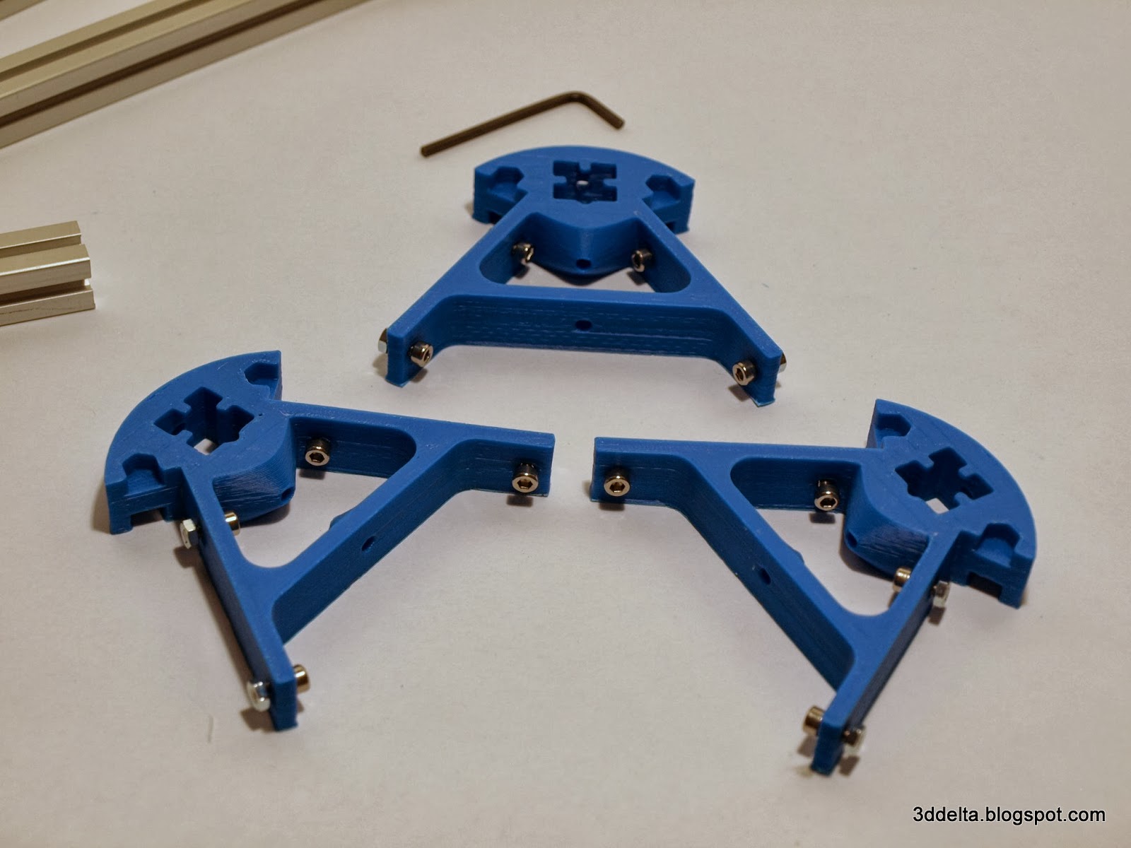
The assembly process is similar with the one of the base. The next views illustrate step by step bringing the printed corners and the aluminum extrusions together.
View 16
 |
View 17
 |
View 18
 |
View 19
 |
View 20
 |
View 21
 |
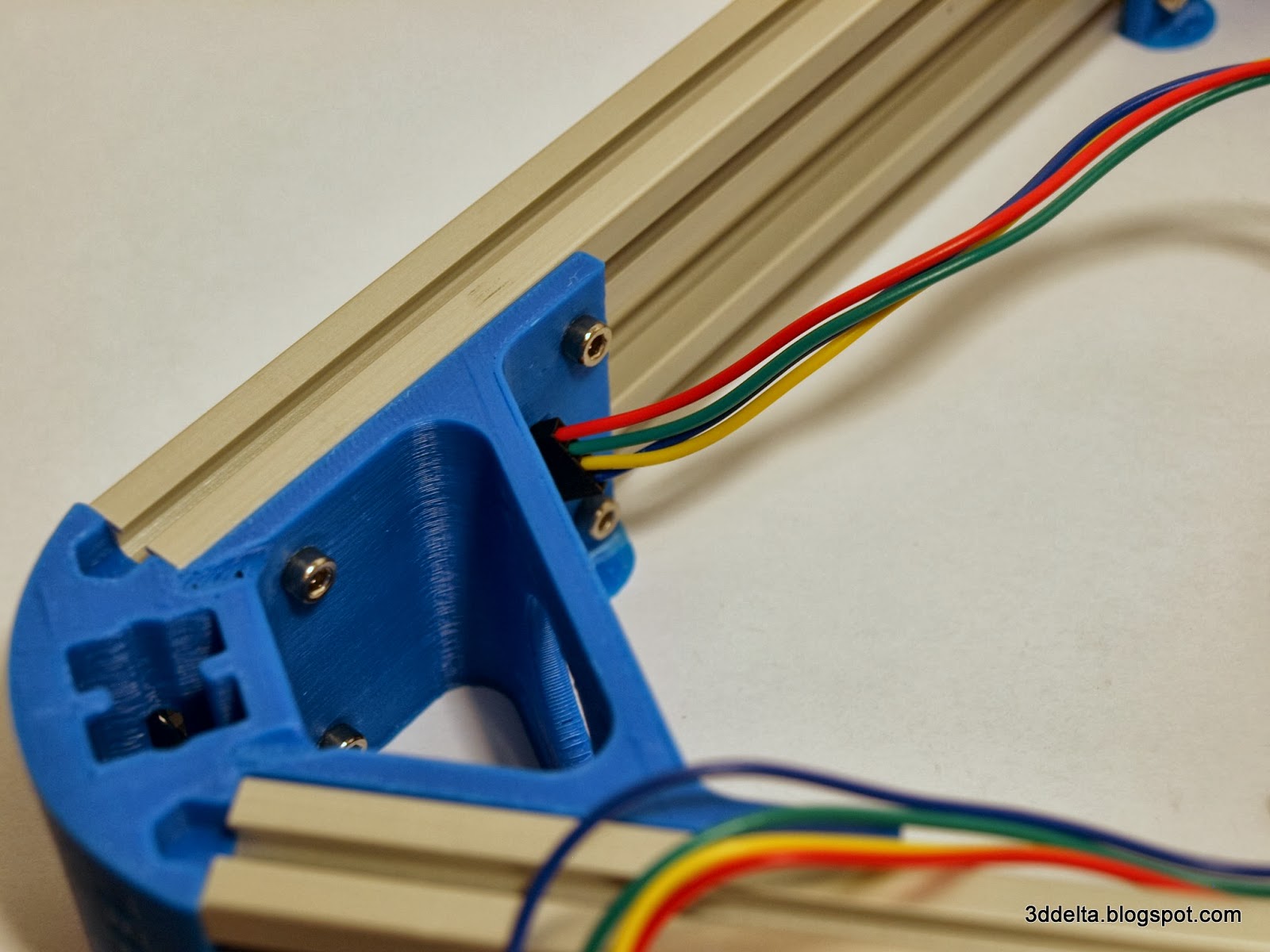
Once all the parts are brought together use the 3mm Allen wrench to tight all the screws and secure the aluminum extrusions to the printed plastic corners.
We are coming back to the base assembly to attach the stepper motors.

I got my Kysan NEMA 17 stepper motors from www.tridiprinting.com (see Mini Kossel BOM page). I like the long wires and the fact the shaft has a flat. This helps securing the GT2 pulleys on the shaft.
I started by inserting the wires through the slots that Johann designed in the printed corners, but I realized that I jumped over an important step. Check view 24 and try to identify what is wrong with that picture?
View 22
 |
View 23
 |
View 24
 |
Answer? The GT2 pulley is missing from the motor shaft. Once attached with screws to the printed corner there is no space to introduce the GT2 pulley on the shaft. So do not attach the motors until you insert the GT2 pulley.
Before you go to far follow the steps from views 25, 26, 27 to attach the GT2 pulley.
View 25
 |
View 26
 |
View 27
 |
Important Note: The GT2 pulley might be a little to tight for the motor shaft. Do not use a hammer to force the pulley down (you can damage the motor bearings). Use a cylindrical file (found in the file set from Harbor Freight Tools ) to enlarge the hole of the pulley. Do not file to much. The pulley should slide on the motor shaft by hand (you will need to adjust the position to trim the belt vertically) without being loose.
I don't know the size of the Allen wrench that I used to tight the pulley securing screws, but I have a full set and it was the smallest (maybe 1.5mm). You can notice in view 26 that I used another Allen wrench to set consistently for all three motors the distance between the pulley and the chassis. It does not matter now what it is, it can be adjusted if needed later.
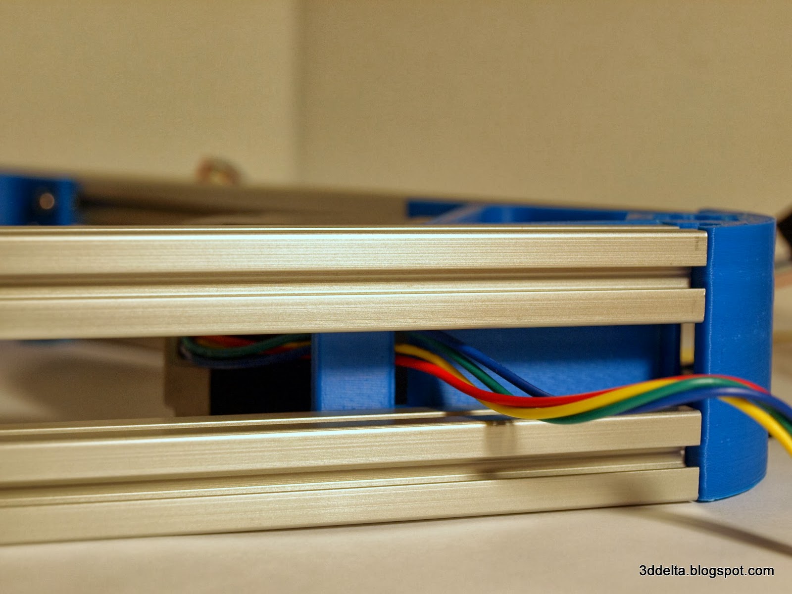
With the pulleys secured thred the cable through the other hole and through the vertical channel of the printed corner. The wires will be covered inside the channel of the aluminum extrusion. After securing the motor to the printed corner with four M3 6mm screws your build should look like my build from view 30.
View 28
 |
View 29
 |
View 30
 |
I will stop here with the base assembly.
Follow me in part 3 of the Phase I - Rectangles and Parallelograms to finally assemble the vertical extrusions rectangle and the effector support rods parallelogram.
Coming soon...
No comments:
Post a Comment