I thought about a title of this building phase and I remembered about Galileo Galilei words "Eppur si muove".
He was talking about the Earth orbiting around the Sun, but at the end of this phase I would to say it about my Kossel 3d Priter before starting the calibration process.
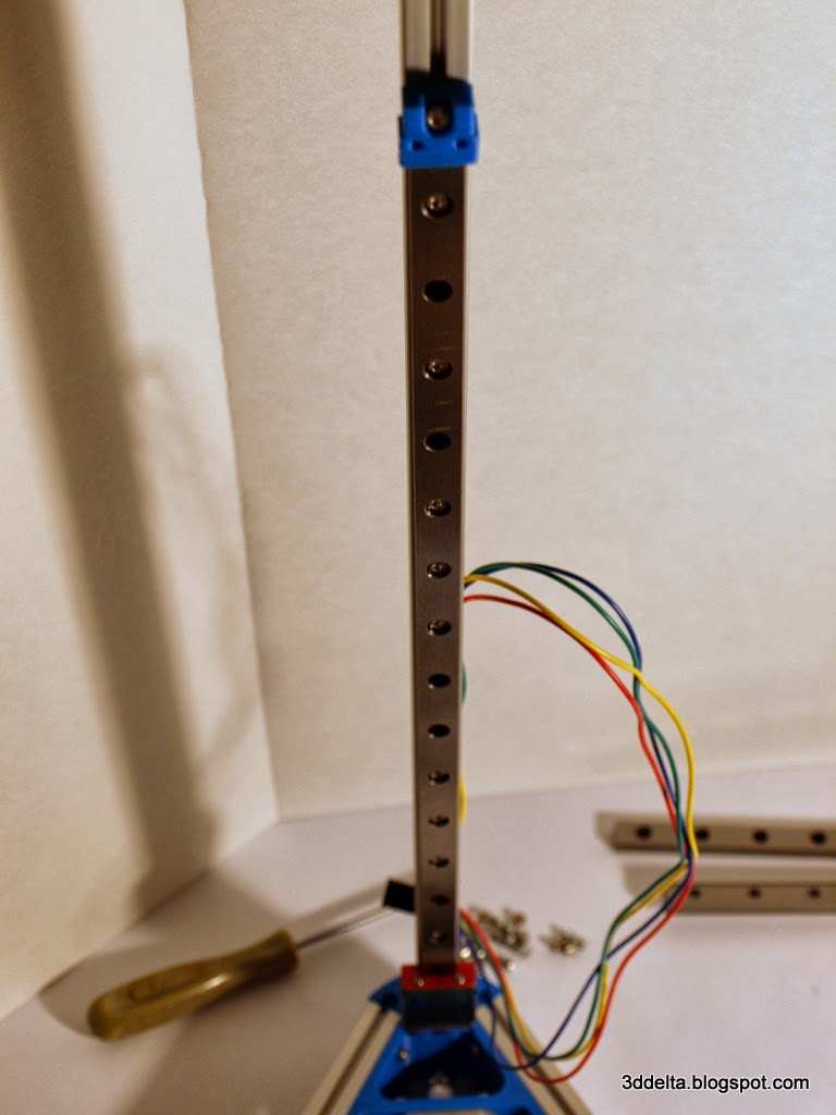
So after couple of weeks of waiting I finally got my linear rails. I did not plat to use all the screws to connect the rails so I choose one on, one off pattern, but the number of holes does not match my pattern, so i got what you can see in the picture.

To fit the linear rails over the vertical towers you will have to remove the top support triangle. Attach the M3 8mm screws to the rails and the six plastic rails end supports. Slide the plastic rails end and the rails as in views 36 and 37.
View 36
 |
View 37
 |
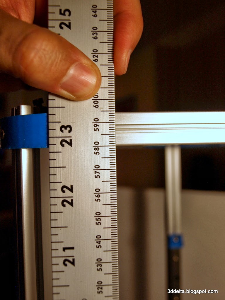
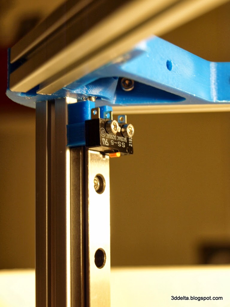
The lineup of the linear rails is not critical, but the alignment of the end-stops is. To align the end-stops I reattached the top triangle, slide it equally by measuring it from the build table and tight the end piece, the one used to attach the end-stop switches, by using a 4mm Allen wrench as spacer. See views below:
View 38
 |
View 39
 |
View 40
 |
After receiving the F623ZZ flanged bearings (they came in set of 10 - so I have 4 left), I assembled the belt idler like the picture below:
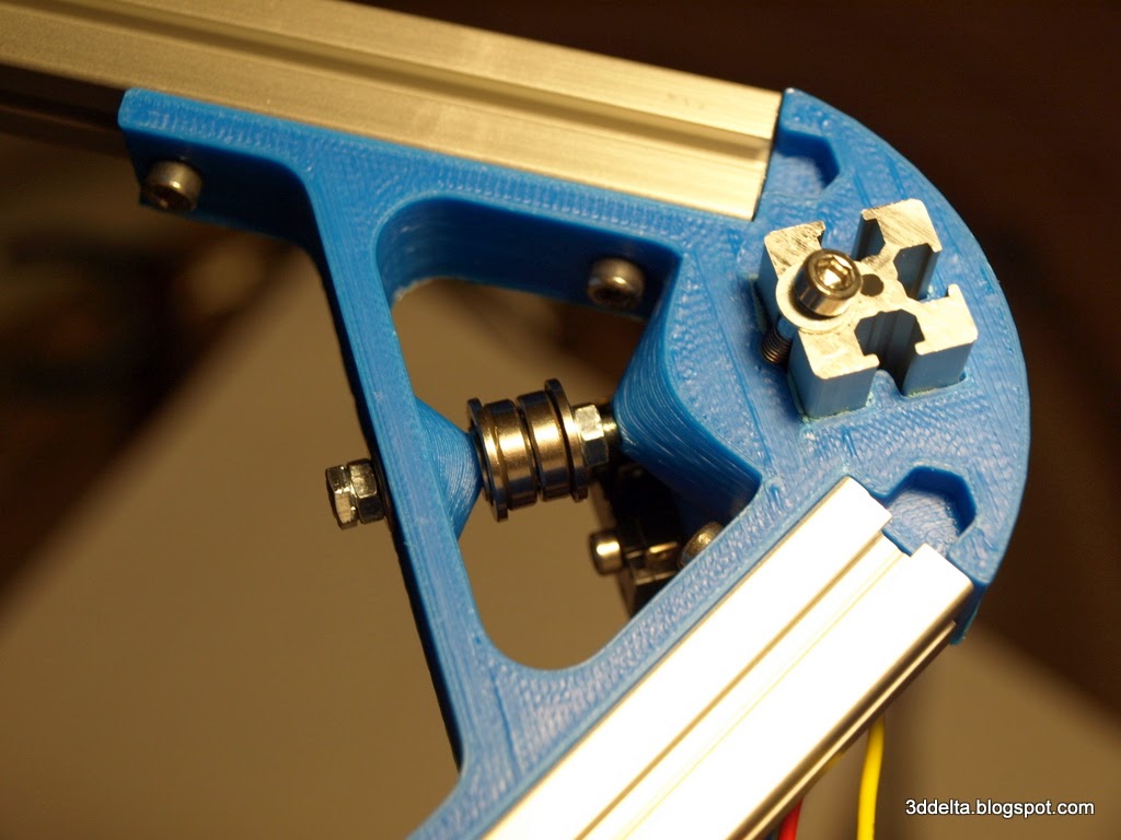
I used a M3 x 30mm screw (a 25mm long will probably fit better) and I added an extra nut and washer at the screw head. Always use an extra washer in between the two flanged bearings, otherwise the space between two flanges is narrower than the belt width and the belt will shift out of the channel.
Next run and cut the belt to the proper length. Do not forget to run the belt through the channel of the carriages attached to the linear rails. To join the two belt ends together I have to give credit to Erik from the Delta robot 3D Printers Google group for the idea. My implementation looks like this:

I used 60mm of the same belt and some zip-ties. The reason behind shifting the position of the zip-ties is keep the belt from shifting to one side.
Next part will cover wiring, prepare your soldering irons!
The top of the frame is mainly for tensioning the belts. No matter how hard you try, or how well you measure you will have to go through several iterations of setting the endstop offsets suck the Z_MAX (specified in firmware) is at the right height when homed.
ReplyDeleteI just realized that when I start the calibration process. My distances on the Z at the base of each tower are different. It is nice that the endstops offset can be adjusted in the firmware. Or an adjustment screw can be screwed in the top of each carriage.
DeleteThanks' for pointing this.