See images below for more details.
View 22
 |
View 23
 |
View 24
 |
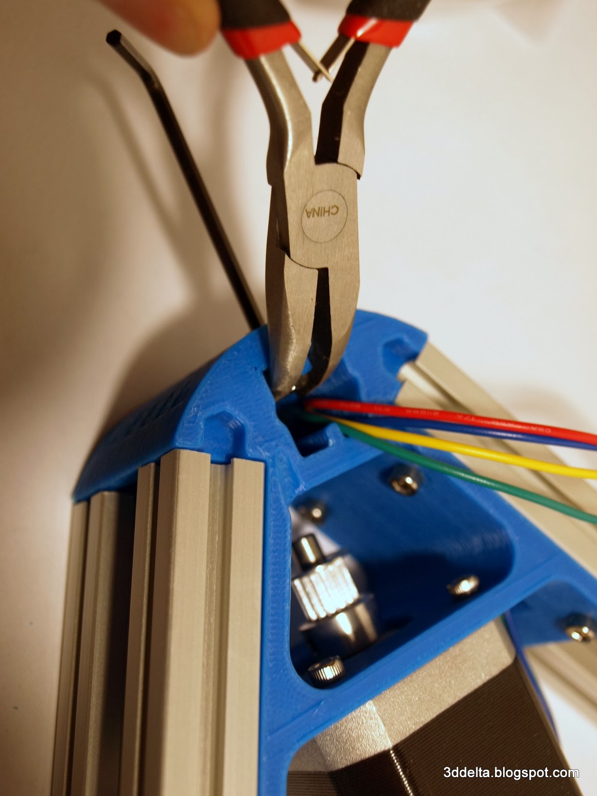
The trickiest part from all the build until now was to insert the vertical towers into the slots. You will have to stir clear of the motor wires and fit them to the extrusion channel. Also fit the M3 nuts into the opposite channel.
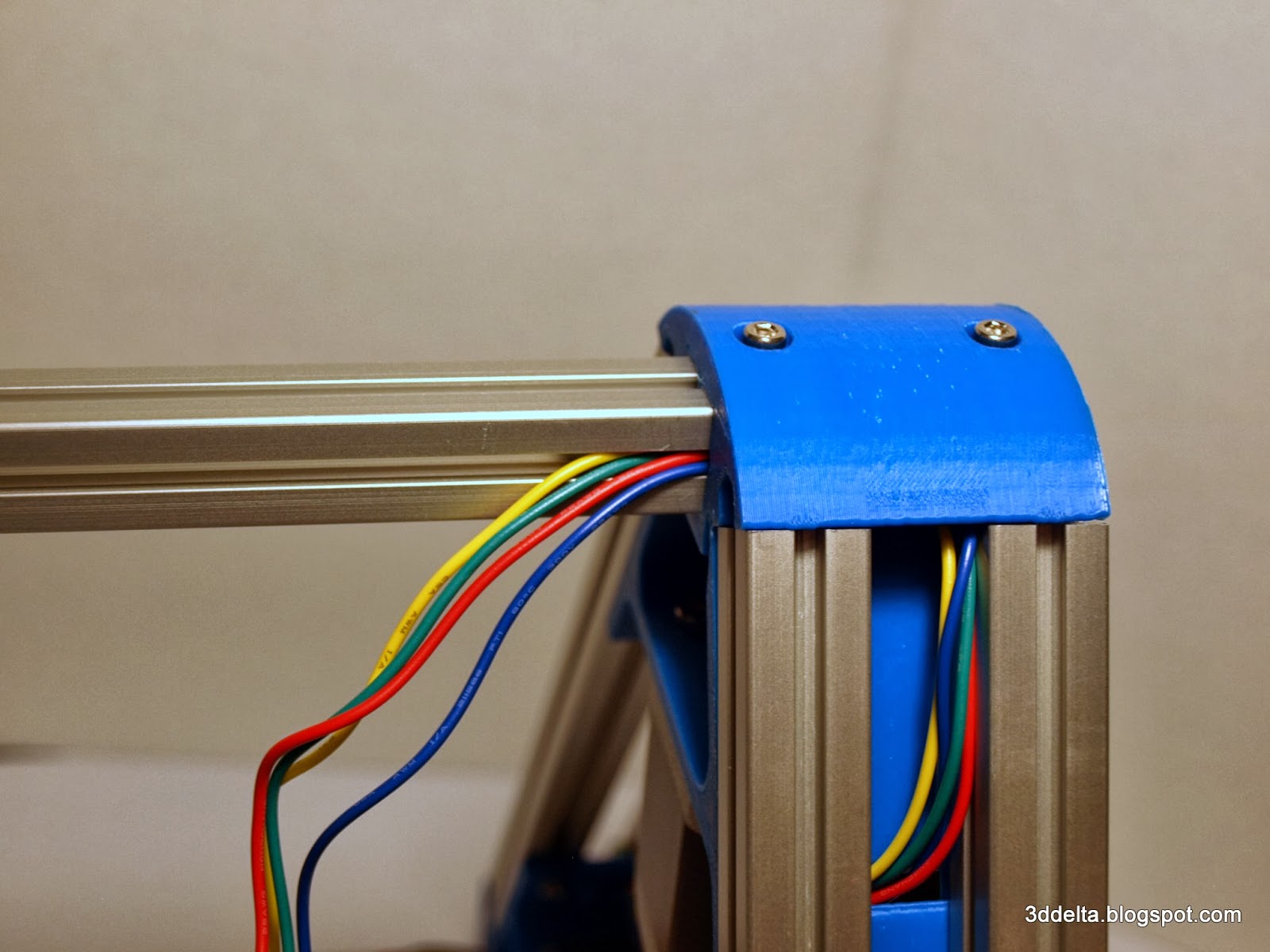
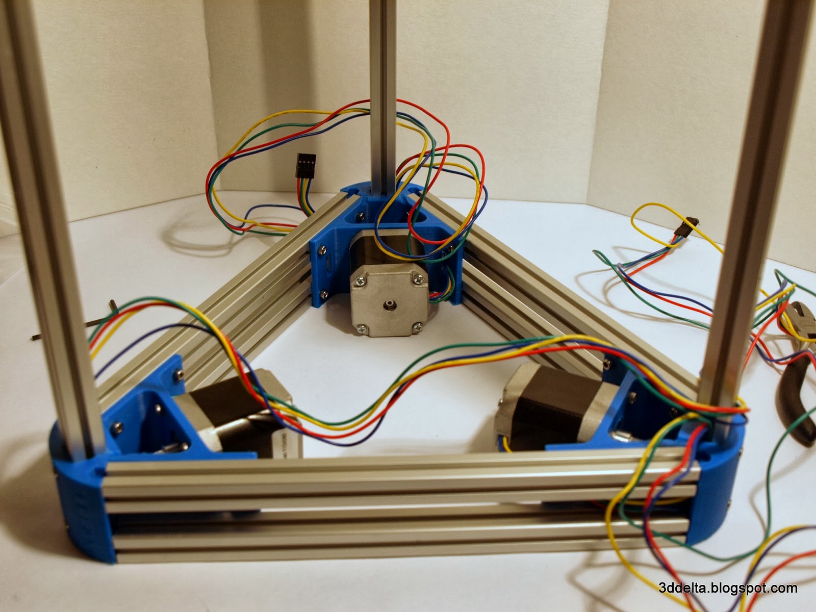
In the end tight and secure the M3 screws with the Allen wrench. Your build should look like mine in views 25 and 26.
View 25
 |
View 26
 |
In the same way add the M3 screw to each of the top corners and temporary attach the top triangle to the vertical towers. (You will have to remove the top to attach the belt idler and tensioner screw.)
Next step will focus on the second part of the title - the parallelograms.
The carriages, support rods and the effector create parallelograms that varies in shape during movement of the carriages. An important characteristic of these parallelograms is to be identical as much as possible. So before you start assembling check the measurements of all the printed parts. See views below. Then start with the part that has the small value, and using a flat fine file create a flat contact surface with the Traxxas joints. File all the pieces equally on left and right contact surface and bring all pieces to the same value.
Note. I got my caliper at Harbor Freight Tools for $9.99 with a coupon.
View 27
 |
View 28
 |
The value is not as critical as to have the same value across all components. My tolerance was +/- 0.05 mm.
You also need to check the length of the support rods. I bought mine already assembled form TRiDPrinting
I check them by assembling all on two M3 long screws and notice if any rods are longer or shorter that the other ones.

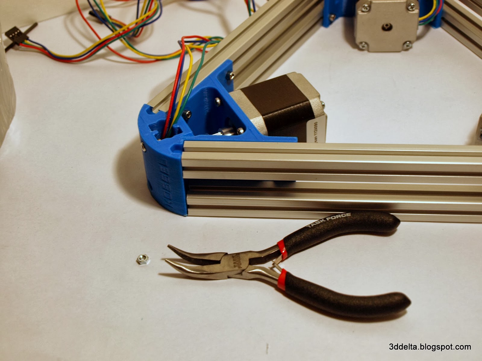
I started assembling from the effector side and prepare 12 M3 25mm screws with M3 nilock nuts to prevent the screws to become loose during printing. I used the same needle nose pliers to insert the nuts in the hexagonal slots.
You also need to check the length of the support rods. I bought mine already assembled form TRiDPrinting
I check them by assembling all on two M3 long screws and notice if any rods are longer or shorter that the other ones.
View 29
I started assembling from the effector side and prepare 12 M3 25mm screws with M3 nilock nuts to prevent the screws to become loose during printing. I used the same needle nose pliers to insert the nuts in the hexagonal slots.
View 30
 |
View 31
 |
View 32
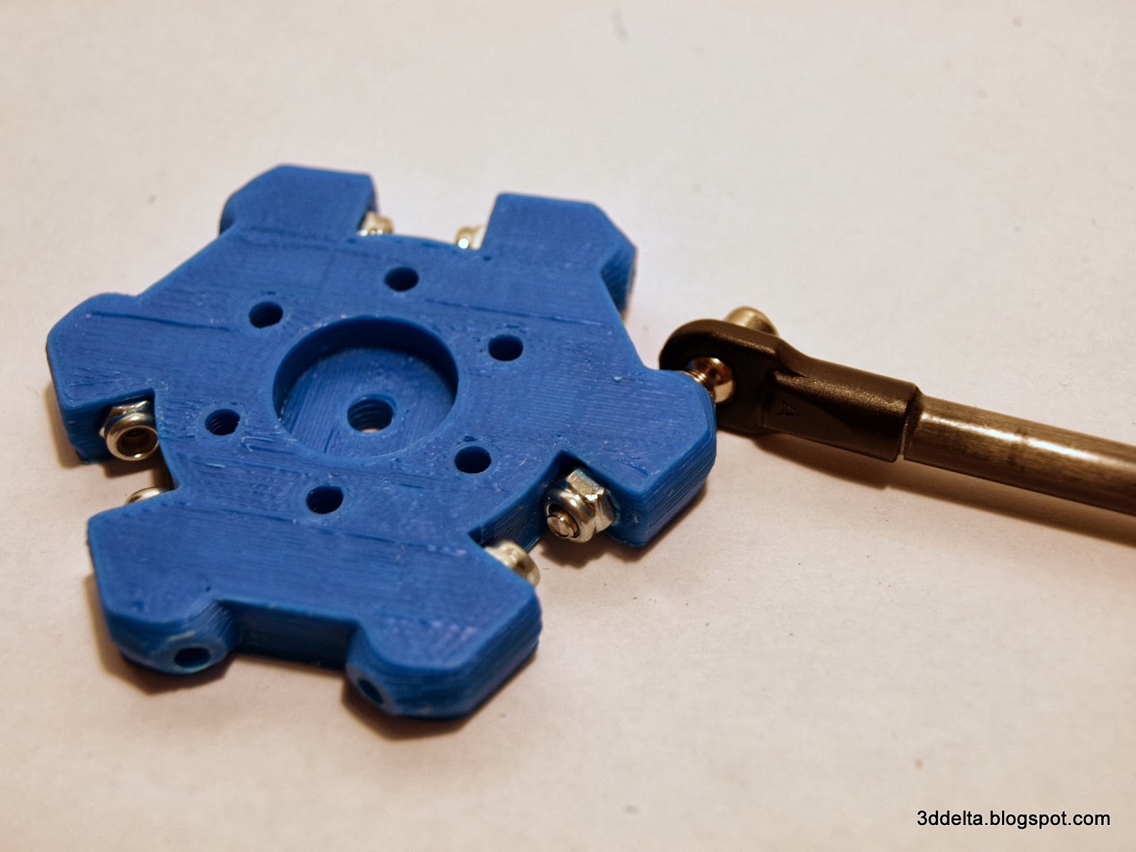 |
Before inserting the nuts check all the screws holes and use a cylindrical file to clean and enlarge the holes to allow the screw to slide in freely. Attach all six support rods, you might need to use the needle nose pliers to keep the nilock nut from spinning if the hexagonal hole is to wide to capture the nut.
Attach the three vertical carriages in the same way. Right now I used the same type of screws (M3 25mm), they reach out into the designed channel, but I don't know how they affect the belt travel.

I did a new set of measurements after I tight the socket screws, and verify the distance between the heads of the screws.
Attach the three vertical carriages in the same way. Right now I used the same type of screws (M3 25mm), they reach out into the designed channel, but I don't know how they affect the belt travel.
View 33
View 34
 |
View 35
 |
The next step will be to add the linear rails (when I will get them) and install the timing belts (when I will get the ball-bearings). This will be covers in Phase II - And yet it moves.
No comments:
Post a Comment